
cdaringe
learnings, nerdisms, bicycles
about
rad
freshawair
up'n'up
pl selector
github diary
dvd.js.org
standup
donut
cowtown
truth.lol
fish.js.org
factorio-type-kit☠
red-or-green☠
senor-salsa☠
Fastener Free Forestboard Features
November 11, 2026
Last month I published forestboard, but I wasn't entirely happy with it. The screen sat too far below the sheet metal plate, and was so off center that it just didn't quite look right. Due to an electrical problem with the first board, I knew that I was going to build up another keyboard anyway, so I decided to take a stab at fixing the screen position.
Sheet metal cutout for the screen.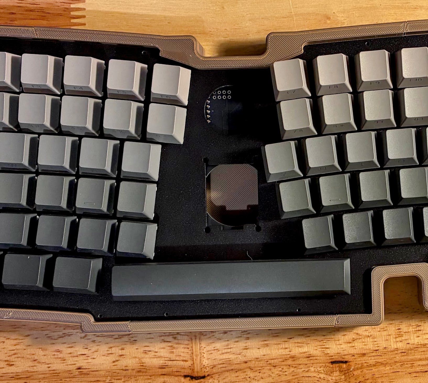
Let's get that screen titled up and centered.
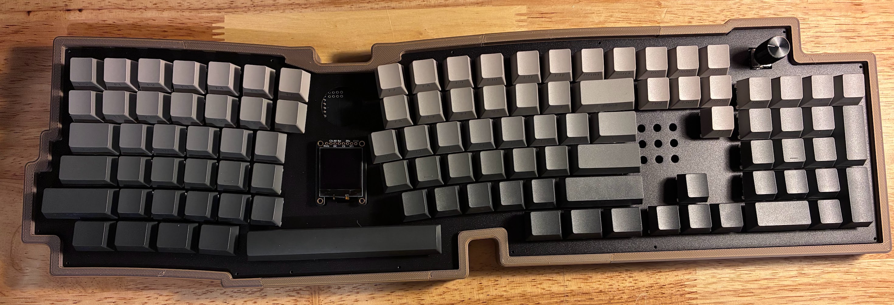
Objective: center the screen & tilt it up so it's easier to read. Stretch goal? Use no fasteners!
I have a history of building things with an unreasonable number of fasteners. Screws, nuts, washers, captured hardware, etc. For this part, I want a snug fit with no extra hardware. 3D printer PLA is pliable enough that I should be able to snap everything together. Snap fits can be tricky--you want strength and flexibility in small parts, and those are easily in conflict. I noticed that OnShape offers a FeatureScript MCP server, so I figured I'd give it a shot too.
Describe, print, repeat
v1 to v5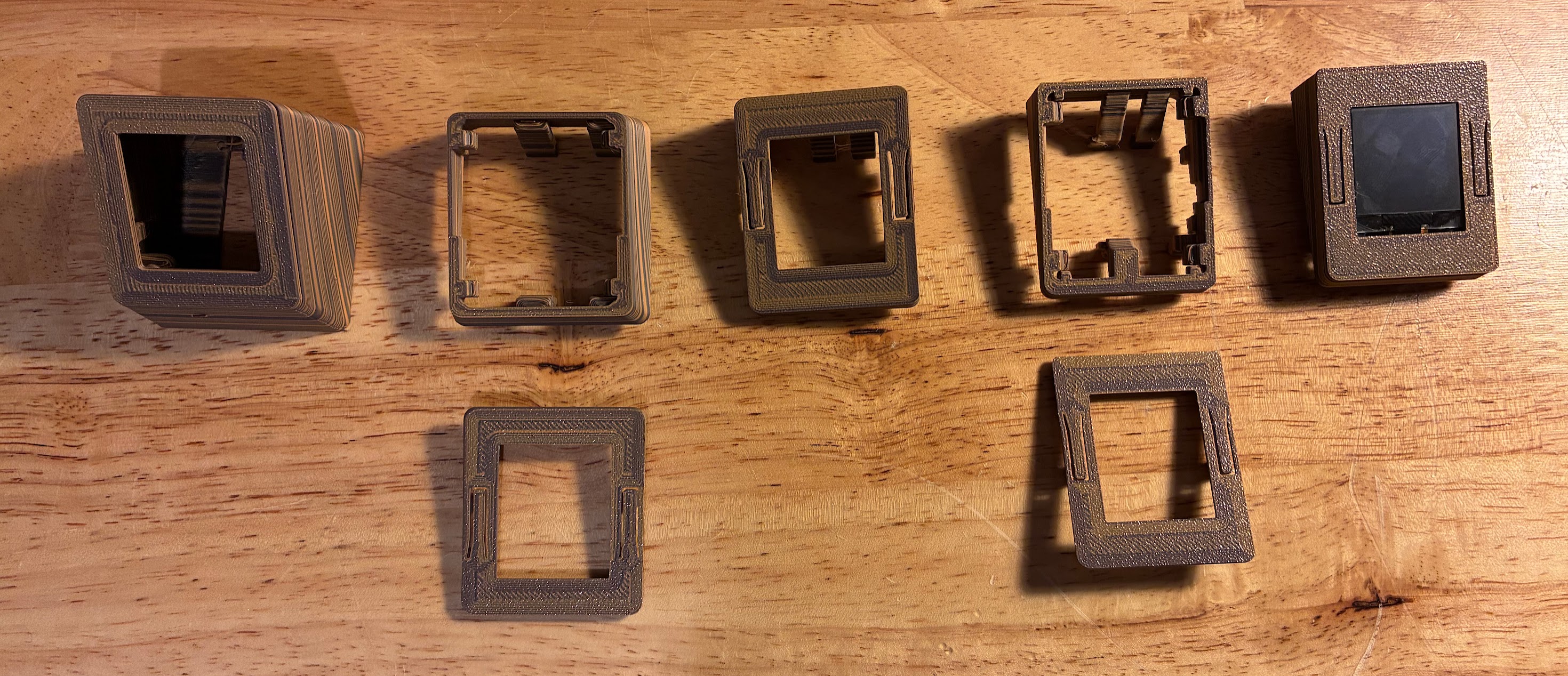
I used Sol 6.1 to help generate each iteration of the mount. I generally wrote no more than one paragraph of prompt text per version. FeatureScript MCP wasn't able to cleanly read existing OnShape sketch geometry, which was a bit odd. Nonetheless, the dimensions of the screen PCB were readily available and I manually fed Sol the sheet metal dims. It got right to work!
v1
v1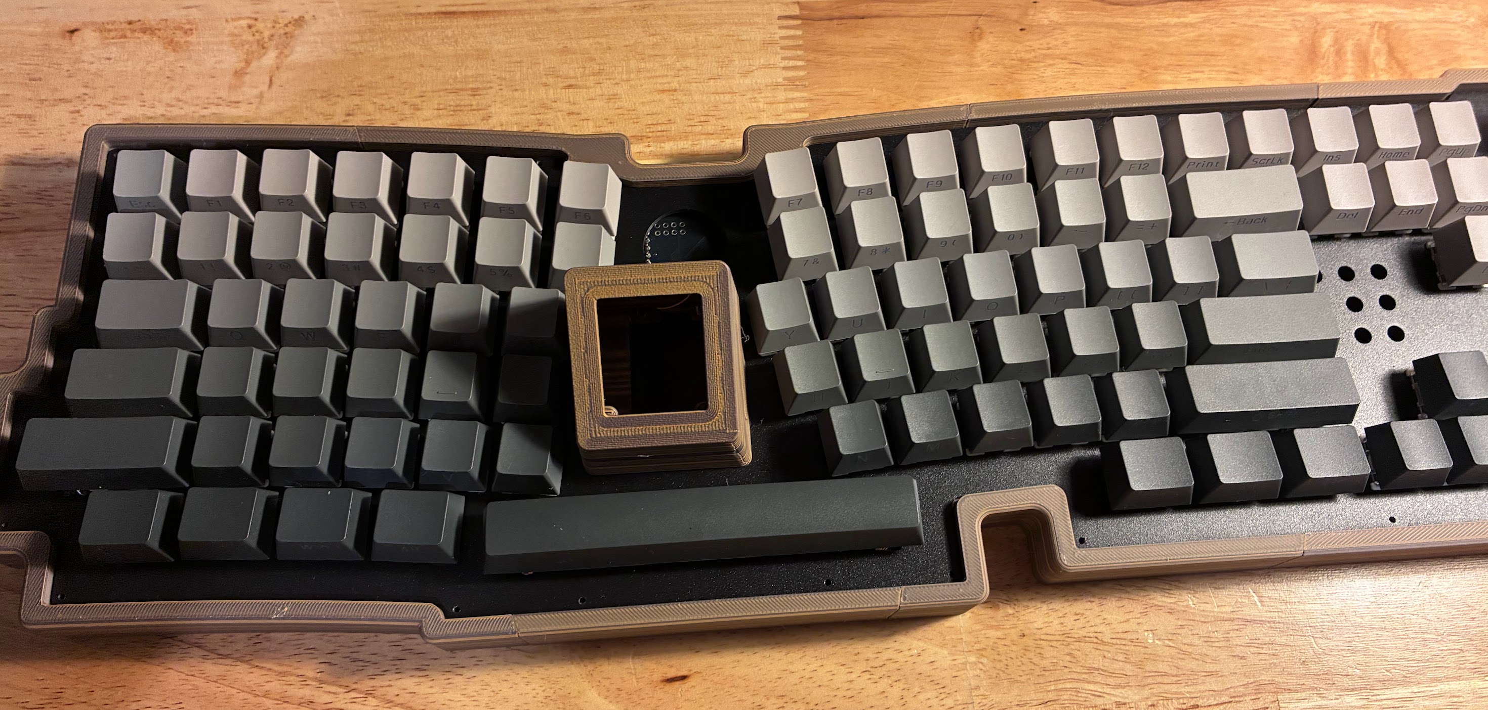
The first version was a quick and dirty prototype only. Garbage in, garbage out. I really wanted to focus on the screen PCB dimensions and the amount of horizontal offset. It was clearly much too big!
V2: clips, but in the wrong place.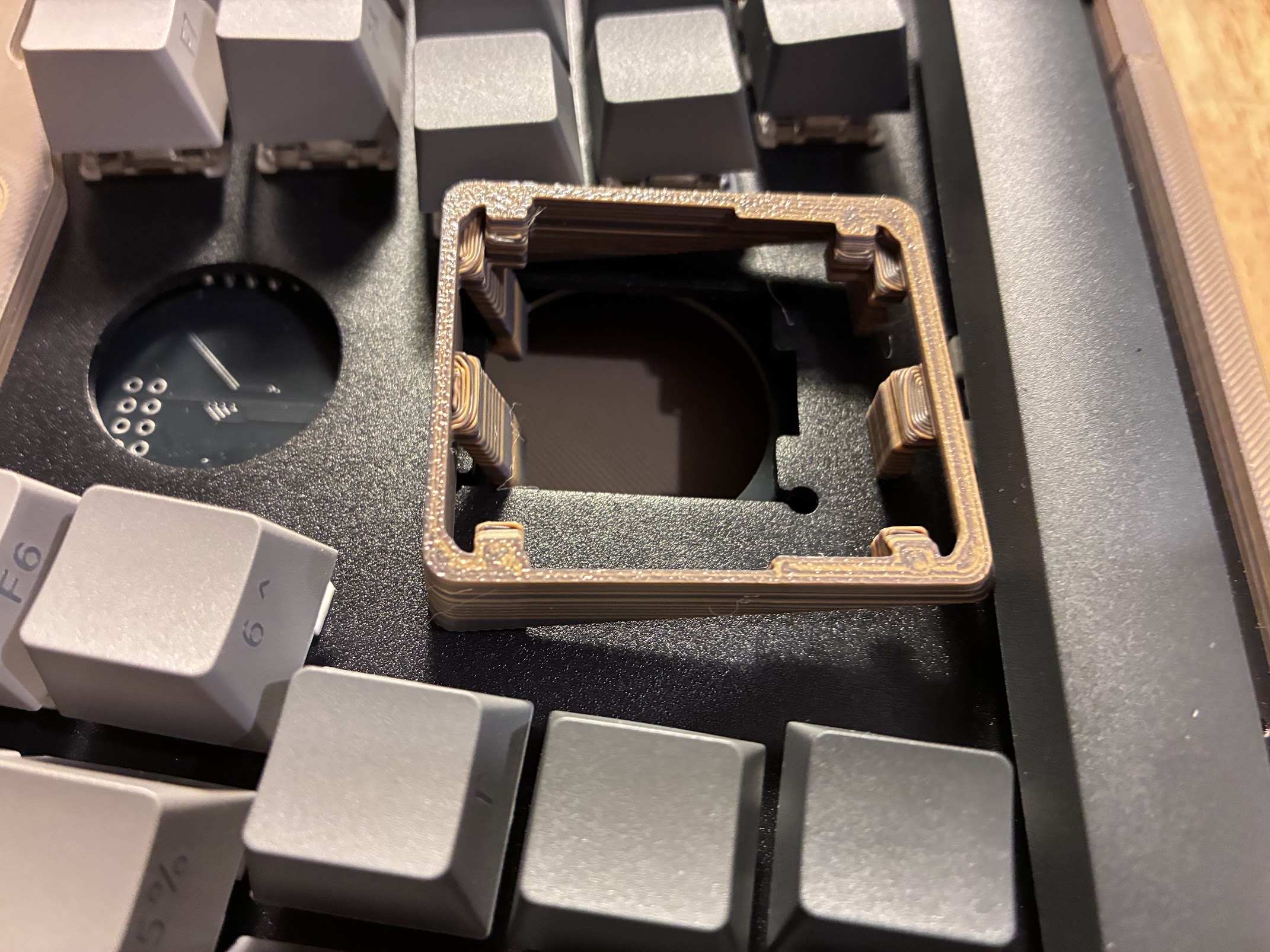
V2 was focused on being lower profile, but the AI ignored the sheet metal dimensions, and I didn't double check it. Whoops!
v3 - working on alignment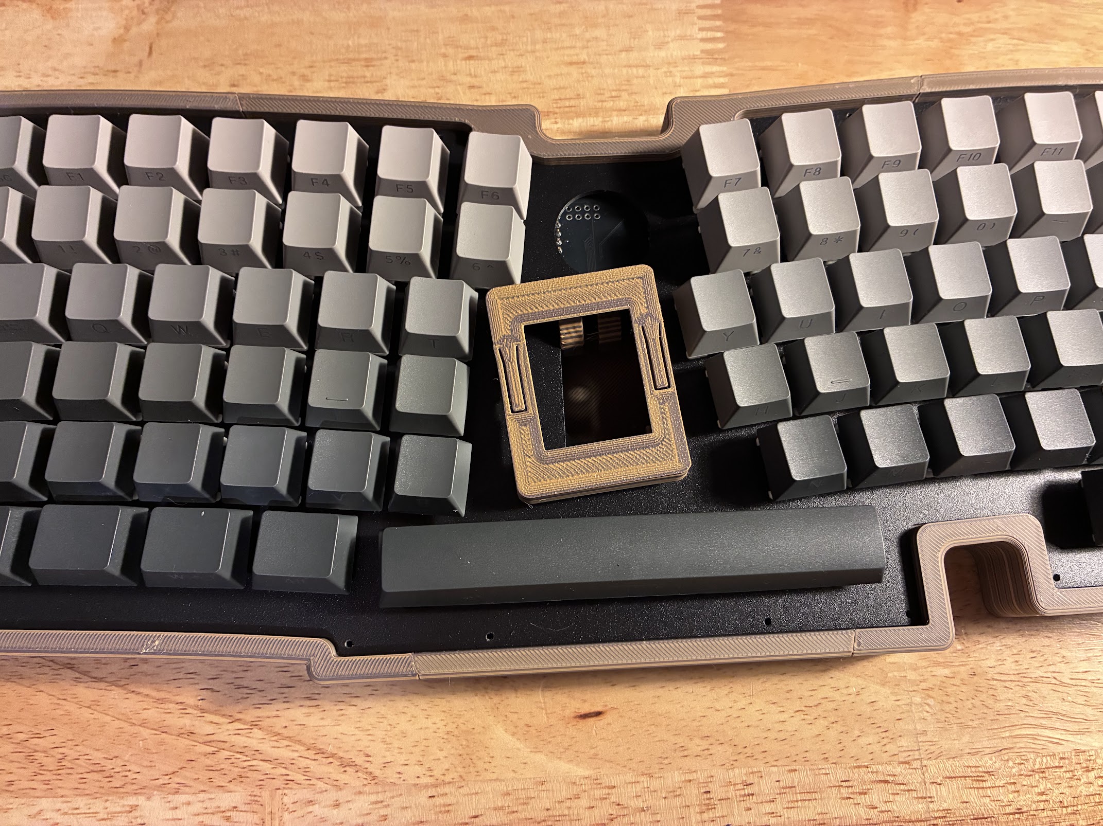
The third version was actually pretty decent! However, there were not enough features to firmly locate the mount in place. It rotated somewhat freely in the sheet metal cavity, so I needed to lock it down. Because the of offset aspect of the mount, it made for some slightly awkward floating geometry to ensure all edges were firmly located. There are some quirky, almost inconspicuous features that actually play a critical role. It was a bit fun to see how few features I could use, and how little plastic I could get away with. I wasn't looking to save on plastic, but it was super convenient to make for nice and speedy prints!
v5 & v4, respectively.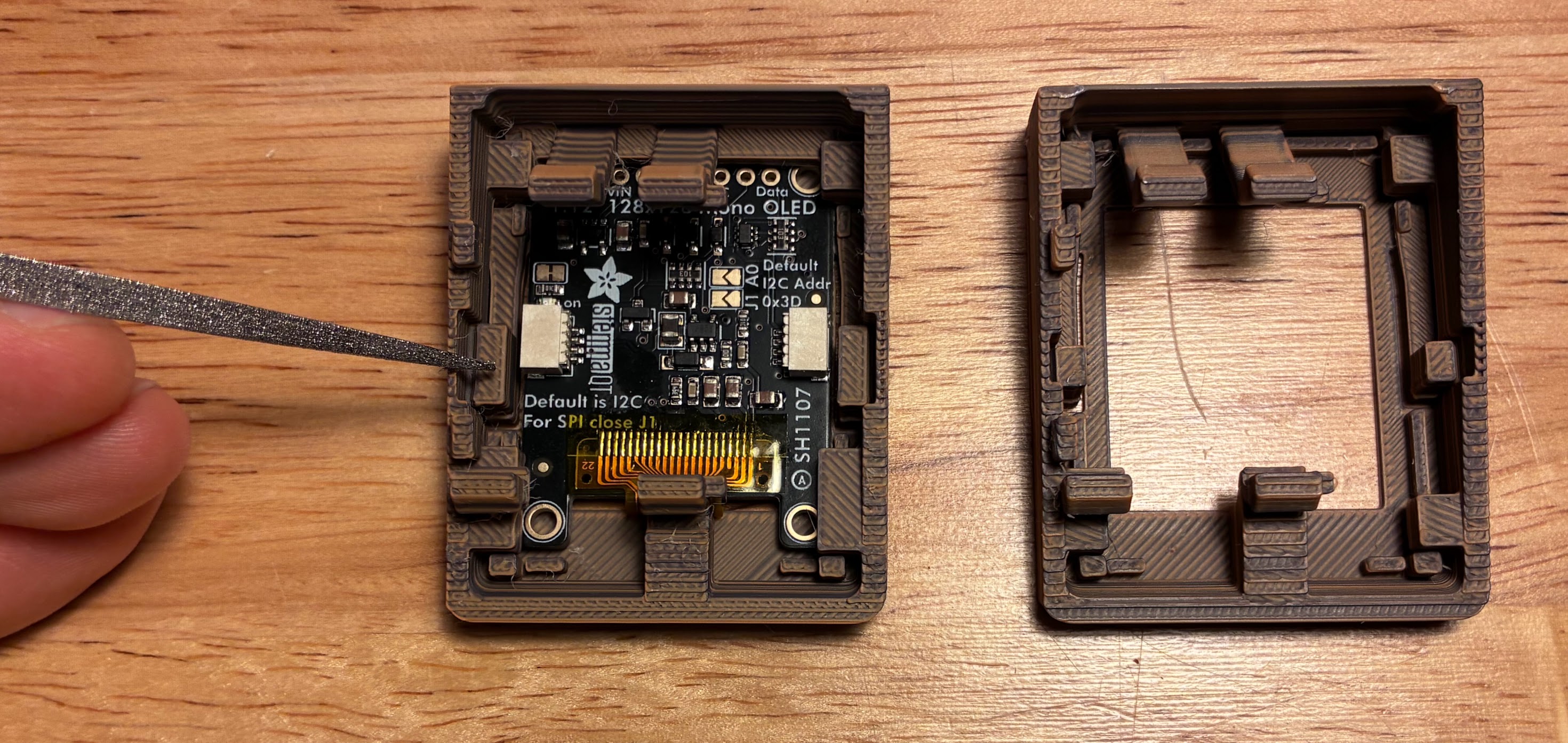
v4 worked fine, but the bezel piece was quite flimsy. You can see me pointing to the bezel clip on the v5 variant--it's substantially larger. The v4 bezel took almost no force to pop off, making the whole thing feel cheap and unfinished. The v5 variant keeps the screen firmly in place, making it feel like a proper, finished product.
v5 in Onshape. Plenty of little features for a little screen.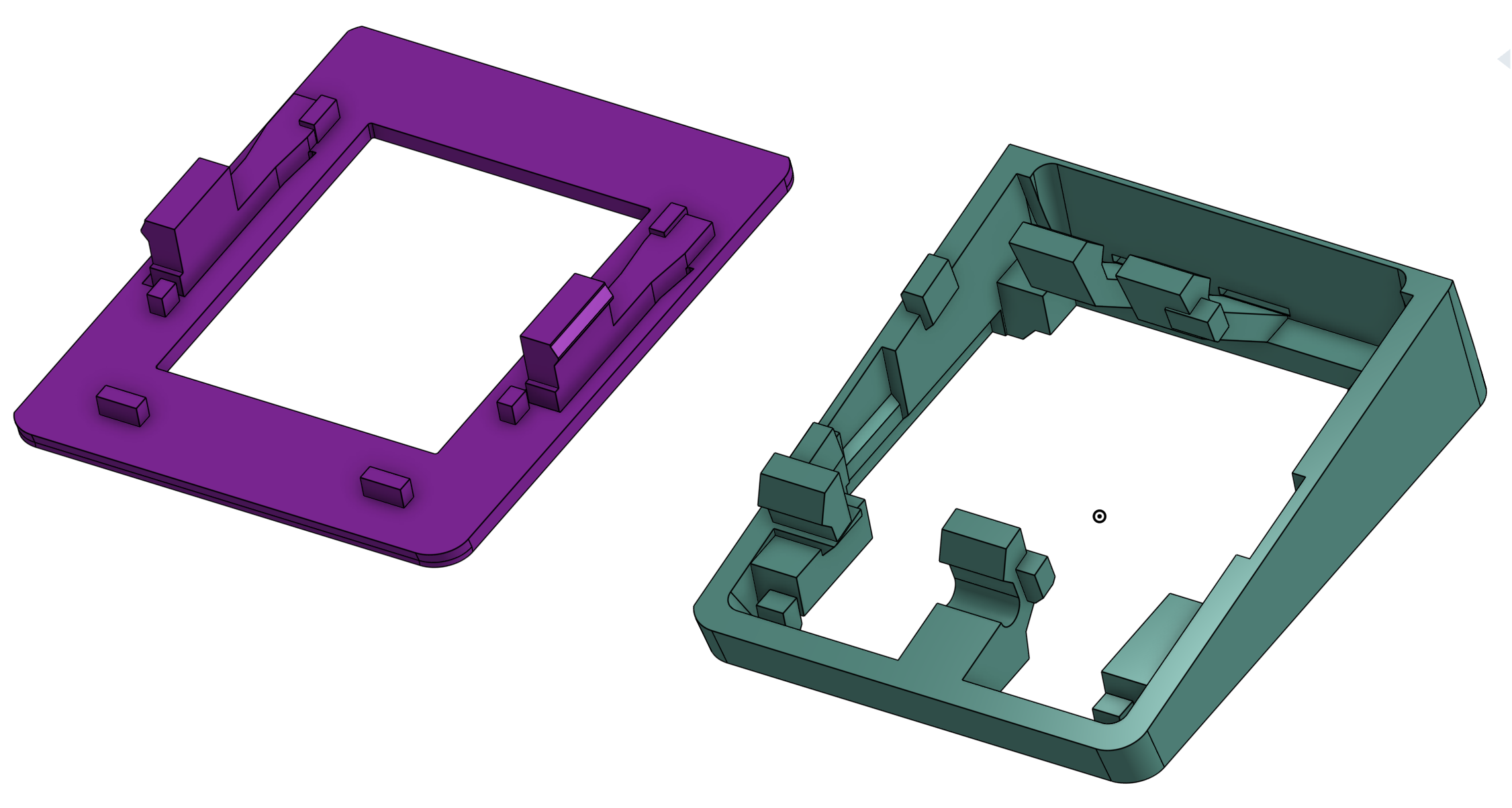
All in all, I probably invested only 15 minutes total for the actual design and CAD aspects of this project. It's a staggeringly low amount of time. I spent plenty of time babysitting the AI, setting up the prints, and troubleshooting fit issues. However, I've never spent so little time on the actual design work. It may seem like just two simple parts--but they really are quite complex! It's precision fit geometry with rigid components and flexible snaps. I'm still floored on how easy it was. Sadly, OnShape gives you only 2.5k total annual API calls. It's absurdly low, so I may have to try out FreeCAD MCP or even just openscad.
v5 in action.More than anything, I'm just very content with my new keyboard. Looks great, sounds great, feels great. It's super unique and is purpose built just for me!